WRspice is a general-purpose circuit simulation program based on the venerable Berkeley SPICE (Simulation Program for Integrated Circuit Engineering). Although completely compatible with modern implementations of Berkeley SPICE, and partially compatible with many commercial extensions, WRspice is an entirely new simulator written in the C++ programming language for ease of development and maintenance with high performance. WRspice includes a built-in Verilog parser/simulator for mixed analog/digital simulations. Verilog is a popular IEEE standard hardware description language used to model digital logic circuits.
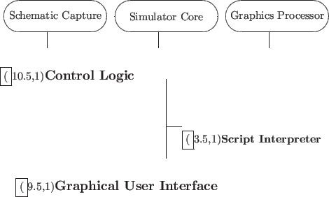
The overall structure of WRspice is shown in Figure 1.1. The core of the program is the numerical analysis kernel, which actually solves the nonlinear circuit equations. This engine is controlled by a large block of logic, which in turn is controlled through interaction with the keyboard and mouse, or under control of a script file, or even under the control of another program. Repeated analyses, or analyses dependent upon the outcome of simulating variables, can be set up through use of control language scripts. Input can be entered as description files, or graphically from a schematic representation. Output can be plotted on the screen, with powerful ability to manipulate and transform the data. The basic user interface is very similar to a UNIX shell, with automatic command completion, a history mechanism, and other features known to UNIX users.
WRspice uses the same basic algorithm to solve the nonlinear circuit equations as the original version of SPICE. This is a modified nodal analysis, where a matrix A is determined, and a solution vector X is obtained from an excitation vector B by inverting the expression AX = B. In WRspice, the coefficients of X are node voltages, and branch currents of voltage sources and inductors. The coefficients of B are independent source currents, plus terms which are added during the linearization process. The coefficients of A are the small-signal admittance parameters of each device, plus factors which relate branch currents to other circuit currents.
When the input description is submitted, WRspice sets the coefficients of the A matrix corresponding to each device in the circuit. The B vector is also defined from knowledge of the source values. The solution vector X is then obtained through an in-place LU decomposition of A. If all circuit elements are linear, then X represents the output vector at the initial time point. However, in general, the circuits contain nonlinear elements, and X at this point can be considered only an approximation to the correct solution. This is because the A matrix contains only first order terms, and approximations of the contributions of higher order terms have been added to the B vector. Initially, these ``predictor'' terms represent an educated guess, however after solving for X, one can obtain more accurate estimates. These better estimates are then incorporated into a new B vector, a new A matrix is obtained, and the LU solution repeated. This iterative process continues until the predictor terms converge to a stable value within an error tolerance. This process is known as Newton's method.
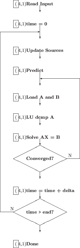
A transient analysis solves the equation set at increments of time over the range specified by the user. The time increment is determined by an algorithm which predicts the maximum allowable time step given past behavior. Clearly, to simulate as rapidly as possible, the number of time steps and iterations should be minimized. There are a number of variables which can be set in WRspice which affect this behavior, and it is difficult to generalize from one circuit to another which are the best conditions. For example, one can lengthen the average time step, however this will generally require more iterations at each time step, which may lead to slower execution time. Also, one can reduce the number of iterations by increasing the error tolerance, however this may result in excessive errors in the output.
Figure 1.2 below shows a flow diagram of the solution algorithm for transient analysis.
Some distributions of WRspice separate the device models from the program, placing them into a dynamically linked library, which is loaded at run-time. In some cases, the user has control of this library and can add or delete devices at will. All device-related information in this manual pertains to the library supplied by Whiteley Research Inc. with the WRspice product. Local system administrators should be consulted for information on locally-added devices.
The default device library contains the devices familiar from SPICE2 and SPICE3, including resistors, capacitors, inductors, mutual inductors, independent and dependent voltage and current sources, lossy and lossless transmission lines, switches, and the five most common semiconductor devices: diodes, BJTs, JFETs, MESFETs, and MOSFETs, plus Josephson junctions, similar to the RSJ model first included in SPICE2 by Jewett[11]. The original device models from SPICE3 are provided, along with a number of third-party models, particularly for MOS transistors.
WRspice is based on JSPICE3, which in turn was derived from SPICE3F4, which developed from SPICE2G.6. While WRspice is being developed to include new features, it will continue to support those capabilities and models which remain in extensive use in the SPICE community.
WRspice is part of the XicTools design system from Whiteley Research, Inc. These tools are designed to be modular, yet interactive. In particular, WRspice will work seamlessly with the Xic graphical front-end for schematic capture, if the Xic program is present. Otherwise WRspice can be utilized in a stand-alone mode. From the Xic graphical editor, WRspice can be called upon to perform simulations, if WRspice is present. In this case, since it is used in a background mode, the WRspice binary can exist on a remote machine.
The XicTools package has been developed primarily under BSD-4.4 Unix (FreeBSD), which is the reference operating system. The tools have been ported to many other UNIX-type operating systems, including Linux, Sun Solaris and SunOS 4.1.x, HPUX, and DEC Alpha-OSF. The tools are also now available for Microsoft Windows.
Unix/Linux releases of WRspice use the GTK toolkit running on the X window system for the graphical user interface. If X is not available, or if the user so chooses, WRspice will run without graphics (other than crude ASCII-mode plots).